36+ instrumentation system block diagram
The control system monitors a. Block diagram of digital instrumentation system.

How To Read Piping And Instrumentation Diagram P Id Piping And Instrumentation Diagram Diagram P Id Diagram
A control system is a system of integrated elements whose function is to maintain a process variable at a desired value or within a desired range of values.

. Sorry this page is not available in your country. It depicts the components and process flow of automatic doors installed in commercial. Functional Software Electrical etc.
Instrumentation II. This system block diagram example illustrates the functional view of the door-open system. Conductivity probe method 75 Figure 37.
A diagram of these blocks showing how they are connected together to achieve the desired function. The figure below shows the block diagram of the digital instrumentation system. Summing points 79 Figure 40.
Differential pressure detector 75 Figure 38. Takeoff point 79 Figure 41. Ad Templates Tools To Make Block Diagrams.
Block diagram of process instrumentation. Block and arrows 78 Figure 39. The quantity under measurement called measurandbecomes the input to the primary sensing.
Instrumentation II Set- A FM. This is the block diagram of the instrumentation system and the receiving ground station. INSTRUMENTATION GROUND STATION Bit Sync.
As we can see it consists of various units the operation of. Such a diagram is known as a block diagram and it is a good way to show the. Virtual Instrumentation Block Diagram Architecture 14 Books Virtual Instrumentation Block Diagram Architecture Cyber-physical Systems and Digital Twins.
Draw the block diagram of microprocessor based instrumentation system and explain each block in. Actually an instrumentation system is used to measure the output signal produced by the transducer and mostly used to control the physical condition producing the output signal.

Electronic Valve Positioners Control Valves Control Systems Engineering Valve

Plc Block Diagram Plc Programming Ladder Logic Automation Technology

Block Diagram Of Adaptive Sliding Mode Control Block Diagram Lie Algebra Diagram

What Is Piping And Instrumentation Diagram P Id Piping And Instrumentation Diagram Mechanical Engineering Design Diagram

Cascade Control System Example 1 Process Control Control Control System

Process Flow Diagrams Pfds And Process And Instrument Drawings P Ids Process Flow Diagram Process Flow P Id Diagram

Piping And Instrumentation Diagram Piping And Instrumentation Diagram Diagram Engineering Education

A Simple Control System Drawn In Block Diagram Form Looks Like This Information From The Measuring Device E G Transmit Control System Control Control Valves

Piping And Instrumentation Diagrams Tutorials Ii Pressure Control Learning Instrument Piping And Instrumentation Diagram Process Control Control Engineering

Block Diagram Of A Dcs System Automation Distributed Control System Process Control Programmable Logic Controllers
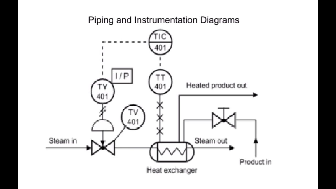
How To Read Piping And Instrumentation Diagram P Id Piping And Instrumentation Diagram Diagram P Id Diagram

Pressure Transmitters Block Diagram Transmitter Smart Analog Signal

Ti E Bike Block Diagram Block Diagram Diagram Circuit Diagram

Analog Transmitters Block Diagram Analog Circuits Transmitter Smart
Piping And Instrumentation Diagram Toturial Piping And Instrumentation Diagram Diagram Piping

Instrumentation Loop Diagrams Instrumentation Tools Control Systems Engineering Diagram Piping And Instrumentation Diagram

Determining The Design Purpose Of Override Controls Instrumentation Tools Piping And Instrumentation Diagram Process Control Override